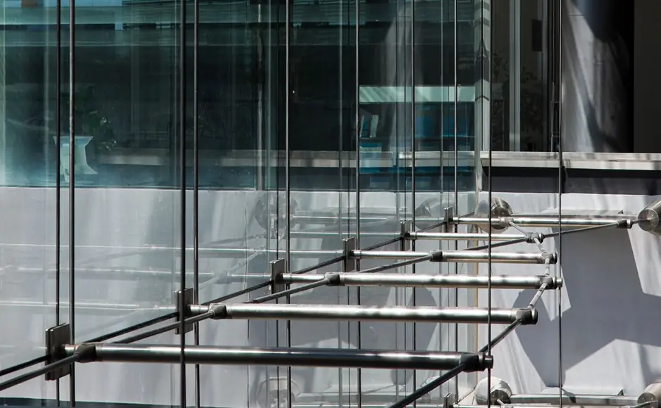
Compare Structural Glass Systems: The Ultimate Engineering Guide
The architectural evolution of modern building envelopes moves toward total transparency. Traditional construction relied on heavy, opaque load-bearing walls. Consequently, these walls divided interior spaces through mass and physical separation. However, contemporary engineering inverts this paradigm. Today, designers transform glass from a secondary infill into a primary structural medium. Modern buildings demand facade systems that support immense loads and resist extreme environmental pressures.
Engineering transparent load-bearing assemblies requires advanced material science and structural mechanics. Unlike ductile metals, glass exhibits brittle behavior with zero capacity for plastic deformation before fracture. Consequently, specifying these systems demands rigorous calculations and finite element modeling. Furthermore, every mechanical connection and silicone joint carries immense consequence. These details dictate long-term safety under dynamic operational loads.
Navigating this specialized domain extends far beyond basic aesthetics. Engineers must reconcile competing physical variables, including wind-induced pressure fluctuations and thermal expansion mismatches. Therefore, a structured approach to evaluation is essential. Moreover, the ability to compare structural glass systems effectively allows teams to balance structural integrity, architectural vision, and economic viability across complex projects.
Understanding “compare structural glass systems”
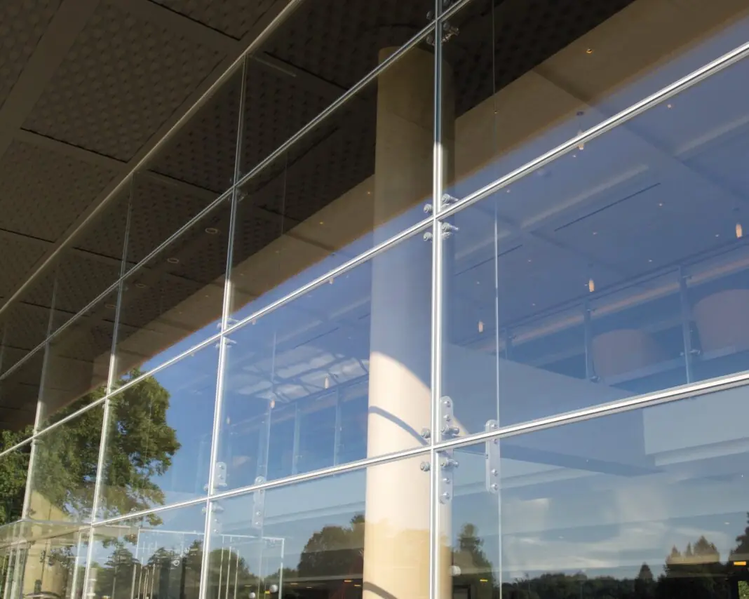
The task to compare structural glass systems involves evaluating distinct engineering configurations. These configurations include glass makeups, interlayer chemistries, and mechanical fastening networks. Furthermore, these systems bear primary loads without conventional metal framing. This process encompasses structural glass fins, point-supported facade assemblies, and walk-on structural floors. Defining an optimal choice requires evaluating structural duty, environmental exposure, and safety mandates.
Misunderstandings and Oversimplication Risks
Common misconceptions regarding structural assemblies stem from superficial market literature. Specifically, non-specialists frequently assume that structural glass is a homogeneous material. They believe it can be sized using standard rules of thumb applicable to steel. In reality, glass strength is governed by a statistical probability distribution. Surface micro-flaws and edge finishing quality heavily influence this strength. Treating glass as a standard commodity introduces severe structural risks. Minor edge chipping can precipitate sudden, catastrophic failure.
Redundancy and Post-Breakage Planning
The risk of oversimplification extends to post-breakage planning. Structural elements must feature explicit fallback load paths. For instance, monolithic tempered glass shatters completely upon failure. Conversely, multi-ply configurations utilizing ionoplast interlayers maintain residual post-breakage integrity. These laminated systems continue supporting loads even after primary lites fracture. A rigorous comparative approach demands evaluating worst-case failure mechanics and environmental degradation.
Deep Contextual Background
The trajectory of structural glass engineering reflects a continuous pursuit of material efficiency. Historically, glass was restricted to small panes supported by heavy timber or stone grids due to low material strength. Later, the development of float glass production revolutionized the industry. This manufacturing technique delivered optically flat, distortion-free sheets at commercial scale, laying the groundwork for modern architectural transparency.
Chemical Processing and Thermal Treatments
Concurrently, advances in chemical processing transformed glass into a high-strength medium. The invention of thermal tempering introduced controlled residual compressive stresses on glass surfaces. This process significantly elevated mechanical bending strength and thermal shock resistance. Subsequent developments introduced advanced polymer interlayers, such as polyvinyl butyral and ionomers. These interlayers enabled the fabrication of robust laminated assemblies.
Computational Simulation Maturity
In parallel, structural engineering methodologies matured from empirical sizing charts to sophisticated simulation techniques. As architects conceptualized daring glass structures, traditional planning methods proved entirely inadequate. Consequently, structural engineering evolved into a specialized discipline. It now requires rigorous finite element analysis, dynamic wind tunnel testing, and precise thermal stress modeling.
Conceptual Frameworks and Mental Models
Successfully executing structural glass engineering requires foundational mental models to structure technical reasoning.
The Statistical Strength Probability Model
Glass does not possess a fixed yield strength like ductile metals. Instead, its mechanical strength follows the Weibull distribution. This distribution reflects failure probability based on the size and frequency of surface micro-flaws. Therefore, engineers must treat glass capacity probabilistically and apply rigorous safety factors.
The Post-Fracture Residual Capacity Paradigm
This framework evaluates structural elements in their damaged condition. For overhead glazing and structural floors, the model mandates clear safety margins. If one ply shatters, the remaining intact plies must safely support design loads for a defined period, preventing collapse.
The Differential Thermal-Structural Compatibility Model
Glass and metal framing exhibit drastically different coefficients of thermal expansion. This model requires engineers to design connection details that accommodate relative movement. Specifically, connections must operate without transferring concentrated shear stresses directly onto brittle glass edges.
The Energy-Dissipation and Load-Sharing Matrix
Structural glass assemblies rarely operate in isolation. This conceptual model analyzes how dynamic loads distribute across point fixings, clamping plates, and structural silicone joints. As a result, stress concentrations remain well below material thresholds.
Key Categories or Variations
When specifying materials for monumental projects, evaluating alternative configurations requires balancing mechanical strength with optical clarity and safety.
-
Glass Fin-Supported Vertical Facades: Systems utilizing vertical, multi-ply laminated glass fins to resist wind loads on expansive transparent facades.
-
Point-Supported (Spider) Glass Assemblies: Facade networks utilizing mechanical stainless steel point fixings countersunk into drilled glass holes.
-
Structural Glass Floor Plates and Mezzanines: Multi-ply laminated walk-on glass panels engineered for high pedestrian live loads with slip-resistant surfaces.
-
Tension Cable-Net and Truss Wall Systems: Lightweight stainless steel cable networks that clamp glass lites in tension to offer flexibility against seismic drift.
-
Laminated Structural Beams and Canopies: Horizontal load-bearing glass beams bonded with high-rigidity interlayers to support dead loads with minimal deflection.
-
Four-Sided Structural Silicone Glazing (SSG): Curtain wall systems where glass lites bond directly to aluminum framing using structural silicone sealants.
-
Unitized Structural Glass Modules: Factory-assembled modular glazing units shipped complete with structural frames and glass to accelerate erection timelines.
| System Option | Primary Structural Mechanism | Main Advantage | Principal Limitation | Ideal Architectural Application |
| Glass Fin Walls | Vertical glass beams resisting wind pressure | Maximum optical transparency, minimal metal obstruction | High structural dead load, specialized handling | Monumental museum atriums, corporate lobbies |
| Point-Supported Spider Systems | Mechanical point fixings at glass corners | Clean flush exterior appearance, flexible movement accommodation | Stress concentrations around drilled holes, maintenance intensive | High-end retail storefronts, cultural pavilions |
| Walk-On Glass Floors | Multi-ply laminated plates with slip-resistant top layer | Vertical spatial connectivity, natural light penetration below | High material thickness, skid-resistance wear over time | Mezzanines, communicating staircases, open floor plates |
| Cable-Net Glass Walls | Pre-stressed stainless steel cable networks | Exceptional seismic drift accommodation, ultra-lightweight frame | Complex installation tensioning, high initial engineering cost | High-rise building entry lobbies, transit hubs |
| Structural Silicone Glazing | High-strength structural silicone adhesive bonding | Continuous weather seal, flush monolithic exterior aesthetic | Strict environmental controls required during factory curing | Commercial office towers, institutional facades |
Realistic Decision Logic
Selecting the appropriate structural glass configuration requires reconciling engineering performance demands with architectural geometry. For instance, for high-load vertical structural fins, ionoplast-laminated low-iron glass is the default choice due to its crystal-clear aesthetics. Conversely, for horizontal structural applications like glass floors, slip-resistant surface treatments are mandatory. Project teams must weigh initial expenditures against long-term safety compliance requirements.
Detailed Real-World Scenarios
Analyzing concrete real-world scenarios illustrates how structural glass engineering functions under severe physical constraints.
A : High-Rise Seismic Zone Atrium Fin Wall
-
Context: A 15-meter-tall vertical glass fin facade located in a high-risk seismic active zone.
-
Constraints: Accommodating massive inter-story structural drift during earthquakes without imparting destructive shear forces.
-
Decision Points: Designing sliding head-retaining slotted connections and flexible structural silicone joints that permit independent lateral frame movement.
-
Failure Modes: Rigidly clamping glass fins directly to floor slabs without slip joints causes glass to crush against concrete during seismic drift.
-
Second-Order Effects: Incorporating dynamic seismic slip joints necessitates ongoing periodic inspection of sliding Teflon bearings and flexible gaskets.
B : Coastal Marine Environment Observation Tower
-
Context: A coastal tourist observation tower exposed to high-velocity salt spray and intense ultraviolet radiation.
-
Constraints: Preventing galvanic corrosion of metal fasteners and withstanding high cyclonic impact loads.
-
Decision Points: Implementing marine-grade stainless steel mechanical point fixings, fluoropolymer-coated framing, and heavy impact-resistant laminated units.
-
Failure Modes: Using incompatible fastener metals in the presence of salt spray causes rapid galvanic corrosion and structural joint loosening.
-
Second-Order Effects: Stringent material specifications for aggressive marine environments escalate upfront capital expenditures and mandate rigorous annual inspections.
C : High-End Retail Flagship Walk-On Mezzanine
-
Context: A multi-story flagship retail store featuring a structural glass mezzanine floor and communicating staircases.
-
Constraints: Concentrated pedestrian live loads and optical transparency requirements between retail levels.
-
Decision Points: Specifying three-ply laminated structural glass flooring with anti-slip top surfaces and structural redundancy.
-
Failure Modes: Utilizing improper surface treatments causes excessive center-point deflection under heavy crowds, inducing micro-cracking at edge supports.
-
Second-Order Effects: High density and thickness of walk-on panels create immense dead loads, requiring specialized sub-framing structural reinforcement.
D : Urban Transit Hub Cable-Net Facade
-
Context: A sprawling railway terminal featuring a flexible cable-net glass wall spanning a passenger concourse.
-
Constraints: Severe dynamic wind loading and continuous vibration from passing trains.
-
Decision Points: Specifying pre-stressed stainless steel cable networks paired with laminated insulating glass units and articulated point fixings.
-
Failure Modes: Inadequate cable tensioning can lead to harmonic resonance under wind gusts, causing progressive fatigue cracking at glass corners.
-
Second-Order Effects: Tension cable networks require specialized hydraulic tensioning equipment during installation and periodic re-calibration over time.
Planning, Cost, and Resource Dynamics
The economic lifecycle of structural glass installations is defined by a complex interplay between capital expenditure and asset value. Direct costs encompass raw material acquisition, precision factory fabrication, heat-soak testing, and specialized installation labor. Indirect costs include extensive pre-construction finite element modeling and regulatory permit reviews.
Spatial Trade-offs and Financial Risk
Opportunity costs manifest clearly in spatial and architectural trade-offs. Opting for traditional opaque structures reduces initial material costs but sacrifices natural daylight penetration. Conversely, investing in structural glass demands substantial upfront capital, but it maximizes usable interior daylighting and enhances real estate value. Furthermore, project variability introduces financial risk. Oversized glass lites and custom curved geometries introduce exponential cost multipliers and extended lead times.
| Cost Category | Primary Components | Financial Impact Drivers | Risk Mitigation Strategy |
| Direct Material Costs | Glass plies, ionomer interlayers, stainless hardware | Custom dimensions, low-iron purity, coating types | Standardizing module widths where geometrically feasible |
| Direct Labor Costs | Specialized shop fabrication, crane erection crews | Labor market rates, certified trade union requirements | Engaging experienced structural glazing specialty contractors |
| Indirect Engineering Costs | FEA modeling, physical laboratory testing, permits | Regulatory strictness, custom design complexity | Conducting early-phase collaborative engineering reviews |
| Operational Lifecycle Costs | Maintenance, inspection, seal replacement, cleaning | Climate severity, glass surface area, access equipment | Designing for service-accessible hardware and joints |
Tools, Strategies, and Support Systems
Executing complex structural glass engineering requires an advanced array of digital tools and physical testing protocols.
-
Finite Element Analysis (FEA) Software: Advanced simulation platforms used to model complex stress distributions and wind-load deflections.
-
Computational Fluid Dynamics (CFD) Software: Analytical tools modeling localized wind turbulence and aerodynamic forces acting on facades.
-
Building Information Modeling (BIM) Suites: Integrated 3D modeling environments enabling precise clash detection between structural glass and anchors.
-
Full-Scale Laboratory Testing Chambers: Physical testing facilities where representative mockups are subjected to dynamic air pressure tests.
-
Residual Stress Analyzers: Optical instruments utilized in factory settings to measure internal tempering stresses and detect optical anisotropy.
-
Non-Destructive Ultrasonic Testing Devices: Field diagnostic tools used to inspect structural silicone joint integrity and detect hidden delamination.
-
Specialized Engineering Design Standards: Authoritative repositories providing baseline calculation methodologies and safety factors.
Limitations of Support Systems
These support systems possess inherent limitations. Digital simulations are only as accurate as boundary condition assumptions provided by engineers. Similarly, laboratory mock-up tests evaluate ideal factory conditions that may not perfectly reflect field environments. Consequently, digital tools must be paired with rigorous on-site quality assurance inspections.
Risk Landscape and Failure Modes
The failure landscape of structural glass installations is unforgiving due to the brittle nature of the material.
Compounding Risks
Failures in structural glass systems are rarely isolated events. Instead, they typically stem from a compounding cascade of minor oversights. For example, an improperly specified setting block can harden prematurely under ultraviolet exposure, transferring dead load stresses onto the edge of a glass lite. When combined with an unmitigated thermal gradient, the compromised glass edge initiates a progressive thermal stress fracture. If drainage channels are simultaneously blocked by debris, water infiltrates structural silicone joints, accelerating adhesive degradation.
Taxonomy of Common Failure Modes
-
Spontaneous Thermal Shatter from Nickel-Sulfide Inclusions: Microscopic impurities in fully tempered glass that expand over time, causing sudden, unprovoked shattering.
-
Adhesive and Structural Silicone Creep: Gradual deformation or bond failure of structural silicone joints under sustained dead loads.
-
Laminated Interlayer Delamination: Separation of polymer interlayers from glass plies due to moisture ingress or ultraviolet degradation.
-
Mechanical Point-Fixing Stress Concentration: Localized high stress around bolt holes leading to star-cracking under dynamic wind loads.
-
Galvanic Corrosion at Metal Interfaces: Electrochemical degradation occurring between dissimilar metals in the presence of trapped moisture.
Governance, Maintenance, and Long-Term Adaptation
The completion of construction initiates an ongoing regime of governance, maintenance, and structural adaptation. Navigating the operational phase requires a comprehensive building handover manual detailing inspection schedules and cleaning protocols. Structural sealants and moving hardware components possess finite operational lifespans—typically ranging from ten to twenty years—requiring proactive inspection and replacement before failure occurs.
Monitoring Programs and Adjustment Triggers
Monitoring programs should establish routine review cycles led by qualified facade engineers. Visual inspections must examine structural silicone joints for signs of tearing or cracking. Advanced diagnostic techniques, such as laser deflection monitoring, can detect internal delamination non-destructively under sustained live loads. Furthermore, adjustment triggers must be explicitly defined within the facility management framework if structural settlement causes brackets to bind.
Layered Maintenance Checklist
-
Quarterly Visual Inspection of Joints: Examine structural silicone and wet-seal joints for signs of cracking, debonding, or biological growth.
-
Semi-Annual Hardware and Fastener Audit: Check torque specifications on mechanical point fixings, clamping plates, and structural anchor bolts.
-
Annual Surface and Drainage Cleaning: Wash structural glass surfaces with non-abrasive solutions and clear all internal drainage paths and weep holes.
-
5-Year Comprehensive Engineering Review: Commission certified structural facade consultants to perform diagnostic testing, including deflection and interlayer adhesion checks.
Measurement, Tracking, and Evaluation
Evaluating ongoing performance and structural integrity requires a balanced framework of quantitative metrics and qualitative indicators. Relying solely on lagging indicators leaves building owners reactive and vulnerable. Therefore, a robust management approach integrates leading indicators that forecast potential vulnerabilities before they manifest as physical failures.
-
Leading Indicators:
-
Factory Quality Audit Compliance Scores: Percentage compliance rates during factory heat-soak testing and lamination quality control checks.
-
Installation Tolerance Verification Logs: Measured deviations from plumb, level, and square during structural erection.
-
Material Batch Traceability Records: Comprehensive logging of glass furnace batches and structural silicone cure dates.
-
-
Lagging Indicators:
-
Structural Deflection Monitoring Data: Sensor measurements quantifying glass panel movement under peak wind and live loads.
-
Sealant Adhesion Peel Test Results: Periodic laboratory testing of extracted sealant samples to verify tensile strength.
-
Maintenance Ticket Volumes: Tracking the frequency and nature of reactive service requests related to joint maintenance.
-
-
Qualitative Signals:
-
Optical Clarity and Distortion Assessment: Visual evaluation of anisotropy and roller wave distortion across varying solar angles.
-
Occupant Comfort and Spatial Perception: Subjective feedback regarding acoustic performance, glare control, and thermal comfort.
-
Documentation Examples
To maintain legal accountability and asset value, facility management teams should archive structured documentation sets:
-
As-Built Structural and Shop Drawings: Finalized, stamped coordination drawings reflecting site-specific engineering modifications.
-
Finite Element Analysis Dossiers: Comprehensive engineering packages validating wind load resistance and seismic capacity.
-
Manufacturer Warranty Schedules: Complete documentation detailing warranties for glass plies, interlayers, and structural adhesives, paired with maintenance logs.
Common Misconceptions and Oversimplifications
-
Myth: Structural glass is an indestructible, permanent material that requires no ongoing engineering oversight.
-
Correction: While durable, structural glass is susceptible to surface damage, stress corrosion cracking, and interlayer degradation over time.
-
-
Myth: All tempered glass options carry identical safety profiles against spontaneous breakage.
-
Correction: Standard tempered glass contains inherent nickel-sulfide inclusions; mitigating this requires specifying heat-soaked tested glass.
-
-
Myth: Increasing glass thickness is the sole solution for solving structural deflection and wind load challenges.
-
Correction: Simply increasing thickness adds dead load; optimizing performance often requires multi-ply laminated configurations with high-rigidity interlayers.
-
-
Myth: Structural silicone glazing is merely an aesthetic detail for achieving a clean exterior look.
-
Correction: Structural silicone is an advanced adhesive engineering system that transfers primary wind and dead loads directly to the building frame.
-
-
Myth: Low-iron glass provides superior structural strength compared to standard float glass.
-
Correction: Low-iron formulations eliminate iron oxides solely to enhance optical clarity; mechanical structural strength remains equivalent to standard float glass.
-
-
Myth: Laminated glass interlayers never degrade when exposed to environmental weathering.
-
Correction: Unprotected glass edges exposed to moisture and UV radiation can experience interlayer delamination over extended lifecycles.
-
-
Myth: Point-supported glass fittings distribute loads uniformly across the entire glass panel.
-
Correction: Point fixings introduce high localized stress concentrations around drilled holes, requiring specialized hardware to prevent stress fractures.
-
Ethical, Practical, or Contextual Considerations
The implementation of structural glass carries profound ethical, environmental, and practical implications. Buildings account for a massive share of global energy consumption, and expansive transparent structures represent thermal transfer challenges. Engineers bear a professional obligation to balance aesthetic desires for total transparency with ecological realities. Unmitigated, highly glazed structures can drastically increase energy demands, straining electrical grids. Furthermore, large expanses of transparent glass present a collision hazard to migratory bird populations, requiring the integration of bird-friendly treatments into planning protocols.
Practically, structural glass engineering must also account for human safety and accessibility. Designing monumental glass structures enhances spatial dignity, but unmanaged glare and thermal discomfort can degrade interior habitability. Ethical engineering demands that safety and environmental stewardship are never subordinated to pure aesthetic minimalism. By approaching structural transparency with intellectual rigor, professionals ensure that modern architecture remains both visually inspiring and structurally bulletproof.
Conclusion
The realization of monumental structural glass architecture requires a decisive departure from superficial design methods. The selection and execution of structural glazing systems represent the culmination of a complex synthesis involving structural engineering, environmental physics, and material science. Navigating this domain successfully requires a thorough understanding of brittle fracture mechanics, thermal-structural dynamics, and economic trade-offs across building lifecycles. By adhering to rigorous documentation standards and anticipating compounding risk factors, professionals ensure that structural glass fulfills its ultimate purpose: redefining spatial boundaries through light while maintaining absolute structural integrity.